Please CLICK below ADD to make prosper this BLOG

Friday, May 22, 2009

BSCI - OSPF Questions

Question 1:

An administrator Pipes in the command router ospf 1 and receives the error message: "OSPF process 1 cannot start." (Output is omitted.) What should be done to correctly set up OSPF?

A - Ensure that an interface has been configured with an IP address
B - Ensure that an interface has been configured with an IP address and is up
C - Ensure that IP classless is enabled
D - Ensure that the interfaces can ping their directly connected neighbors

Answer: B

Question 2:

During a recent OSPF election among three routers. RTA was elected the DR and RIB was elected the BDR, as seen in the graphic. Assume that RTA fails, and that RIB takes the place of the DR while RTC becomes the new BDR. What will happen when PTA comes back online?

OSPF_DR_DBR

A - RTA will take the place of DR immediately upon establishing its adjacencie
B - RTA will take the place of DR only if RTB fails
C - RTA will take the place of DR only if both RTB and RTC fail
D - A new election will take place establishing an all new DR and BDR based on configured priority levels and MAC addresses

Answer: C

Question 3:

Refer to the exhibit. During the process of configuring a virtual link to connect area 2 with the backbone area, the network administrator received this console message on R3:
*Mar 1 00:25:01.084: %OSPF-4-ERRRCV: Received invalid packet: mismatch area ID, from backbone area must be virtual link but not found from 20.20.20.1, Serial 0

How should the virtual link be configured on the OSPF routers to establish full connectivity between the areas?

OSPF_virtual_link

A - R1(config-router)# area 1 virtual-link 30.30.30.3
R3(config-router)# area 1 virtual-link 20.20.20.1
B - R1(config-router)# area 1 virtual-link 20.20.20.2
R3(config-router)# area 1 virtual-link 30.30.30.2
C - R1(config-router)# area 0 virtual-link 1.1.1.1
R3(config-router)# area 2 virtual-link 3.3.3.3
D - R1(config-router)# area 1 virtual-link 3.3.3.3
R3(config-router)# area 1 virtual-link 1.1.1.1
E - R1(config-router)# area 1 virtual-link 2.2.2.2
R3(config-router)# area 1 virtual-link 2.2.2.2

Answer: D

Explanation:

When designing a multi-area OSPF network, all areas should be connected to the backbone area. However, there may be instances when an area will need to cross another area to reach the backbone area like area 2 in this case. A virtual link has the following two requirements:

+ It must be established between two routers that share a common area and are both ABRs.
+ One of these two routers must be connected to the backbone.

In this case, two routers that satisfy the above requirements are R1 and R3. The syntax for creating a virtual link across an area is:

area virtual-link

The area-id is the number of the transit area, in this example Area 1 and neighbor-router-id is the IP address of the highest loopback interface configured or can be manually set on the neighboring router.

Question 4:

As shown in the exhibit ,OSPF is configured over a Frame Relay network. All PVCs are active. However, P4S1 and P4S3 fail to see all OSPF routes in their routing tables. The show ip ospf neighbor command executed on P4S2 displays the state of the neighbors. In order to fix the problem , what should be done?

OSPF_NBMA_Frame_Relay

A - The neighbor command should be configured under the OSPF routing process on all routers
B - The ip ospf network broadcast command should be configured on each Frame Relay interface
C - The ip ospf network non-broadcast command should be configured on each Frame Relay interface
D - The ip ospf priority value on the spoke routers should be set to 0

Answer: D

Explanation:

In an NBMA network topology, neighbors are not discovered automatically. OSPF tries to elect a DR and a BDR due to the multi-access nature of the network, but the election fails since neighbors are not discovered because NBMA environment doesn't forward broadcast and multicast packets. Neighbors must be configured manually to overcome these problems.

Also, additional configuration is necessary in a hub and spoke topology to make sure that the hub routers, which have connectivity with every other spoke router, are elected as the DR and BDR. You must set the spoke interfaces to an OSPF priority of zero, this ensures that the spokes will not become the DR or BDR.

Question 5:

The following exhibit shows ipv6 route output. What would the metric be for a summary route that summarizes all three OSPFv3 routes displayed?

cost_of_summary_route

A - 160
B - 140
C - 120
D - 100

Answer: D

Explanation:

The cost of the summarized routes is the highest cost of the routes being summarized. In fact, in the old RFC 1583 standard, the cost of the summary route was the cost of the lowest metric. But when OSPF was updated in RFC 2178 and RFC 2328, the summary route should have the same cost as the highest-cost summarized route. In this case, the highest-cost is 100 according to the second entry.

Question 6:

Study the exhibit below carefully. In order to summarize all routes from area 0 to area 1, what must be configured on the router?

area_range_summary_OSPF

A - area 0 range 172.16.96.0 255.255.224.0
B - area 1 range 172.16.96.0 255.255.224.0
C - area 1 range 172.16.96.0 255.255.0.0
D - area 0 range 172.16.96.0 255.255.255.0

Answer: A

Thursday, May 21, 2009

CCNP lAB-BSCI - EIGRP Questions

Question 1:

Which three statements about the EIGRP routing protocol are true? (Choose three)

A - EIGRP sends periodic hello packets to the multicast IP address 224.0.0.9
B - EIGRP sends periodic hello packets to the multicast IP address 224.0.0.10
C - EIGRP supports five generic packet types. including hello, update, query, reply, and ACK packets
D - EIGRP supports five generic packet types, including hello, database description (DBD), link-state request (LSR), link-state update (LSU), and LSAck
E - E. EIGRP will form a neighbor relationship with another peer even when their K values are mismatched
F - A. EIGRP will not form a neighbor relationship with another peer when their K values are mismatched

Answer: B, C, F

Question 2:

After DUAL calculations, a router has identified a successor route, but no routes have qualified as a feasible successor. In the event that the current successor goes down, what process will EIGRP use in the selection of a new successor?

A - EIGRP will find the interface with the lowest MAC address
B - The route will transition to the active state
C - The route will transition to the passive state
D - EIGRP will automatically use the route with the lowest feasible distance (FD)
E - EIGRP will automatically use the route with the lowest advertised distance (AD)

Answer: B

Question 3:

Refer to the exhibit. Routers R1 and R2 have established a neighbor relationship and are exchanging routing information. The network design requires that R1 receive routing updates from R2, but not advertise any routes to R2. Which configuration command sequence will successfully accomplish this task?

neighbor_relationship_distribute_list

A - R1(config)# router eigrp 1
R1(config-router)# passive-interface serial 0

B - R2(config)# router eigrp 1
R2(config-router)# passive-interface serial 0

C - R1(config)# access-list 20 deny any
R1(config)# router eigrp 1
R1(config-router)# distribute-list 20 out serial 0

D - R2(config)# access-list 20 deny any
R2(config)# router eigrp 1
R2(config-router)# distribute-list 20 out serial 0

E - R1(config)# access-list 20 permit any
R1(config)# router eigrp 1
R1(config-router)# distribute-list 20 in serial 0

F - R2(config)# access-list 20 permit any
R2(config)# router eigrp 1
R2(config-router)# distribute-list 20 in serial 0

Answer: C

Explanation:

We can not use passive-interface to accomplish this task because the "passive-interface..." command (in EIGRP or OSPF) will shut down the neighbor relationship of these two routers (no hello packets are exchanged). And to filter routing updates we should configure a distribute list on R1 with an access list that deny all and apply it to the outbound direction so that R1 can receive but can not send routing updates.

Question 4:

EIGRP has been configured to operate over Frame Relay multipoint connections. What should the bandwidth command be set to?

A - the CIR rate of the lowest speed connection multiplied by the number of circuits
B - the CIR rate of the lowest speed connection
C - the CIR rate of the highest speed connection
D - the sum of all the CIRs divided by the number of connections

Answer: A

Explanation:

If the multipoint network has different speeds allocated to the VCs, take the lowest CIR and simply multiply it by the number of circuits. This is because in Frame-relay all neighbors share the bandwidth equally, regardless of the actual CIR of each individual PVC, so we have to get the lowest speed CIR rate and multiply it by the number of circuits. This result will be applied on the main interface (or multipoint connection interface).

Question 5:

EIGRP_Active_state

Refer to the exhibit. EIGRP is configured on all routers in the network. On a basis of the show ip eigrp topology output provided, what conclusion can be derived?

A - Router R1 can send traffic destined for network 10.6.1.0/24 out of interface FastEthernet0/0
B - Router R1 is waiting for a reply from the neighbor 10.1.2.1 to the hello message sent out before it declares the neighbor unreachable
C - Router R1 is waiting for a reply from the neighbor 10.1.2.1 to the hello message sent out inquiring for a second successor to network 10.6.1.0/24
D - Router R1 is waiting for a reply from the neighbor 10.1.2.1 in response to the query sent out about network 10.6.1.0/24

Answer: D

Explanation:

From the output, we notice that there is an active route (A) and the reply status flag (r) was set. An active EIGRP route is the state when a network change occurs and a feasible successor is not found by a EIGRP router for a given route (10.6.1.0/24); and the reply status flag (r) means that R1's queries were sent out to the neighbors asking for routing information to the 10.6.1.0/24 network but hasn't received a reply yet. Therefore the answer A - router R1 can send traffic destined for network 10.6.1.0/24 is not correct because router R1 can't find a path to that network. Answers B and C are not correct because R1 doesn't send a hello message but a query asking for routing information to the desired network.

Saturday, May 16, 2009

CCNP LAB EIGRP - SHOW IP EIGRP TOPOLOGY ALL-LINKS

Here you will find answers to EIGRP Simlet question

Question:

Refer to the exhibit. BigBids Incorporated is a worldwide auction provider. The network uses EIGRP as its routing protocol throughout the corporation. The network administrator does not understand the convergence of EIGRP. Using the output of the show ip eigrp topology all-links command, answer the administrator's questions.

simlet_show_ip_eigrp_topology_all_links

Question 1:

Which two networks does the Core1 device have feasible successors for? (Choose two)

A - 172.17.0.0/30
B - 172.17.1.0/24
C - 172.17.2.0/24
D - 172.17.3.0/25
E - 172.17.3.128/25
F - 10.140.0.0/24

Answer: A F

Explanation:

To understand the output of the "show ip eigrp topology all-links command" command, let's analyze an entry (we choose the second entry because it is better for demonstration than the first one)

FeasibleDistance_and_AdvertisedDistance

The first line tells us there is only 1 successor for the path to 10.140.0.0/24 network but there are 2 lines below. So we can deduce that one line is used for successor and the other is used for another route to that network. Each of these two lines has 2 parameters: the first one ("156160" or "157720") is the Feasible Distance (FD) and the second ("128256" or "155160") is the Advertised Distance (AD) of that route.

The next thing we want to know is: if the route via 172.17.10.2 (the last line) would become the feasible successor for the 10.140.0.0/24 network. To figure out, we have to compare the Advertised Distance of that route with the Feasible Distance of the successor's route, if AD <>

After understanding the output, let's have a look at the entire output:

simlet_show_ip_eigrp_topology_all_links_2

Because the question asks about feasible successor so we just need to focus on entries which have more paths than the number of successor. In this case, we find 3 entries that are in blue boxes because they have only 1 successor but has 2 paths, so the last path can be the feasible successor.

By comparing the value of AD (of that route) with the FD (of successor's route) we figure out there are 2 entries will have the feasible successor: the first and the second entry. The third entry has AD = FD (30720) so we eliminate it.

Question 2:

Which three EIGRP routes will be installed for the 172.17.3.128/25 and 172.17.2.0/24 networks? (Choose three)

A - 172.17.3.128.25 [90/28160] via 172.17.1 2, 01:26:35, FastEthernet0/2
B - 172.17.3.128/25 [90/30720] via 172.17.3.2, 01:26:35. FastEthemet0/3
C - 172.17.3.128/25 [90/30720] via 172.17.10.2, 01:26:35. FastEthernet0/1
D - 172.17.2.0/24 [90/30720] via 172.17.10.2, 02:10:11, FastEthernet0/1
E - 172.17.2.0/24 [90/28160] via 172.17.10.2, 02:10:11. FastEthernet0/1
F - 172.17.2.0/24 [90/33280] via 172.17.3.2, 02:10:11. FastEthernet0/3

Answer: B C D

Explanation:

First indicate the positions of these networks:

simlet_show_ip_eigrp_topology_all_links_3

Network 172.17.3.128/25 has 2 successors, therefore the two paths below are both successors.

Network 172.17.2.0/24 has only 1 successor, therefore the path lies right under it is the successor.

Question 3:

Which three networks is the router at 172.17.10.2 directly connected to? (Choose three)

A - 172.17.0.0/30
B - 172.17.1.0/24
C - 172.17.2.0/24
D - 172.17.3.0/25
E - 172.17.3.128/25
F - 172.17.10.0/24

Answer: C E F

Explanation:

simlet_show_ip_eigrp_topology_all_links_4

First, we should notice about the entry in the orange box, it shows that the network 172.17.10.0/24 is directly connected with this router and has a FD of 28160. So we can guess the networks that directly connected with router at 172.17.10.2 will be shown with an AD of 28160. From that, we find out 3 networks which are directly connected to the router at 172.17.10.2 (they are green underlined). The network 172.17.10.0/24 is surely directly connected to the router at 172.17.10.2 (in fact it is the network that links the router at 172.17.10.2 with Core1 router).

CCNP LAB - BSCI - IPv6 OSPF Virtual Link Sim

Question:
Acme is a small export company that has an existing enterprise network that is running IPv6 OSPFv3. Currently OSPF is configured on all routers. However, R4's loopback address (FEC0:4:4) cannot be seen in R1's IPv6 routing table. You are tasked with identifying the cause of this fault and implementing the needed corrective actions that uses OSPF features and does no change the current area assignments. You will know that you have corrected the fault when R4's loopback address (FEC0:4:4) can ping from R1 to R4 loopback address.


Answer and Explanation:

To troubleshoot the problem, first issue the show running-config on all of 4 routers. Pay more attention to the outputs of routers R2 and R3

The output of the "show running-config" command of R2:

!

ipv6 router ospf 1

router-id 2.2.2.2

log-adjacency-changes

!


The output of the "show running-config" command of R3:

!

ipv6 router ospf 1

router-id 3.3.3.3

log-adjacency-changes

area 54 virtual-link 4.4.4.4

!


We knew that all areas in an Open Shortest Path First (OSPF) autonomous system must be physically connected to the backbone area (Area 0). In some cases, where this is not possible,we can use a virtual link to connect to the backbone through a non-backbone area. The area through which you configure the virtual link is known as a transit area. In this case, the area 11 will become the transit area. Therefore, routers R2 and R3 must be configured with the area virtual-link command.

Configure virtual link on R2 (from the first output above, we learned that the OSPF process ID of R2 is 1):

R2>enable
R2#configure terminal
R2(config)#ipv6 router ospf 1
R2(config-rtr)#area 11 virtual-link 3.3.3.3

Save the configuration:

R2(config-rtr)#end
R2#copy running-config startup-config

(Notice that we have to use neighbor router-id 3.3.3.3, not R2's router-id 2.2.2.2)

+ Configure virtual link on R3 (from the second output above, we learned that the OSPF process ID of R3 is 1 and we have to disable the wrong configuration of "area 54 virtual-link 4.4.4.4"):

R3>enable
R3#configure terminal
R3(config)#ipv6 router ospf 1
R3(config-rtr)#no area 54 virtual-link 4.4.4.4
R3(config-rtr)#area 11 virtual-link 2.2.2.2

Save the configuration:

R3(config-rtr)#end
R3#copy running-config startup-config

You should check the configuration of R4, too. If it has the command of "area ... virtual link ..." then remove it.

After finishing the configuration don't forget to ping between R1 and R4 to make sure they work well!

Friday, May 8, 2009

BSCI latest pass4sure


BSCI Latest Pass4sure 3.12
B
SCI Latest Pass4sure 3.10
BSCI
Latest Pass4sure 2.93

GUYZ in the next couple of days i will also Include LABS AND SIMS which is on the pass4sure so plz keep access thiz blog and click on any AD's by google thank u.....!

if you guyz any problem plz leave your comment or message me on your left CHAT ROLL box thank you and share information as well thank u

Thursday, April 30, 2009

Squirrel Mail Configuration File SCRIPT


Squirrel Mail Configuration File SCRIPT (LINK HERE)

guyz its a simple script to configure your Linux-squirrel mail server.
if i have anything wrong in this script or u have to share any information regarding this script or other Linux information Please shared with us, POST YOUR MESSAGE or EMAIL me at voasa1@gmail.com

Monday, April 27, 2009

VPN CONNECTION, on any OPERATING SYSTEM

wanna create VPN connection on any (Operating sytem, OS)


Please click ON above link which is mention in Ads By google:
www.strongvpn.com Unlimited bandwidth VPN or click on www.strongvpn.com
There are eight basic steps in setting up remote access for users with the Cisco ASA.
  • Step 1. Configure an Identity Certificate
  • Step 2. Upload the SSL VPN Client Image to the ASA
  • Step 3. Enable AnyConnect VPN Access
  • Step 4. Create a Group Policy
  • Step 5. Configure Access List Bypass
  • Step 6. Create a Connection Profile and Tunnel Group
  • Step 7. Configure NAT Exemption
  • Step 8. Configure User Accounts

So let’s get started!

Step 1. Configure an Identity Certificate

Here I am creating a general purpose, self-signed, identity certificate named sslvpnkey and applying that certificate to the “outside” interface. You can purchase a certificate through a vendor such as Verisign, if you choose.

corpasa(config)#crypto key generate rsa label sslvpnkey
corpasa(config)#crypto ca trustpoint localtrust
corpasa(config-ca-trustpoint)#enrollment self
corpasa(config-ca-trustpoint)#fqdn sslvpn. mycompany.com
corpasa(config-ca-trustpoint)#subject-name CN=sslvpn.mycompany.com
corpasa(config-ca-trustpoint)#keypair sslvpnkey
corpasa(config-ca-trustpoint)#crypto ca enroll localtrust noconfirm
corpasa(config)# ssl trust-point localtrust outside

Step 2. Upload the SSL VPN Client Image to the ASA

You can obtain the client image at Cisco.com. As you choose which image to download to your tftp server, remember that you will need a separate image for each OS that your users have. After you select and download your client software, you can tftp it to your ASA.

corpasa(config)#copy tftp://192.168.81.50/anyconnect-win-2.0.0343-k9.pkg flash

After the file has been uploaded to the ASA, configure this file to be used for webvpn sessions. Note that if you have more than one client, configure the most commonly used client to have the highest priority. In this case, we’re using only one client and giving it a priority of 1.

corpasa(config)#webvpn
corpasa(config-webvpn)#svc image disk0:/anyconnect-win-2.3.0254-k9.pkg 1

Step 3. Enable AnyConnect VPN Access

corpasa(config)#webvpn
corpasa(config-webvpn)#enable outside
corpasa(config-webvpn)#svc enable

Step 4. Create a Group Policy

Group Policies are used to specify the parameters that are applied to clients when they connect. In this case, we’ll create a group policy named SSLClient. The remote access clients will need to be assigned an IP address during login, so we’ll also set up a DHCP pool for them, but you could also use a DHCP server if you have one.

corpasa(config)#ip local pool SSLClientPool 192.168.100.1-192.168.100.50 mask 255.255.255.0
corpasa(config)#group-policy SSLCLient internal
corpasa(config)#group-policy SSLCLient attributes
corpasa(config-group-policy)#dns-server value 192.168.200.5
corpasa(config-group-policy)#vpn-tunnel-protocol svc
corpasa(config-group-policy)#default-domain value mysite.com
corpasa(config-group-policy)#address-pools value SSLClientPool

Step 5. Configure Access List ByPass

By using the sysopt connect command we tell the ASA to allow the SSL/IPsec clients to bypass the interface access lists.

corpasa(config)#sysopt connection permit-vpn

Step 6. Create a Connection Profile and Tunnel Group

As remote access clients connect to the ASA, they connect to a connection profile, which is also known as a tunnel group. We’ll use this tunnel group to define the specific connection parameters we want them to use. In our case, we’re configuring these remote access clients to use the Cisco AnyConnect SSL client, but you can also configure the tunnel groups to use IPsec, L2L, etc.

First, let’s create the tunnel group SSL Client:

corpasa(config)#tunnel-group SSLClient type remote-access

Next, we’ll assign the specific attributes:

corpasa(config)#tunnel-group SSLClient general-attributes
corpasa(config-tunnel-general)#default-group-policy SSLCLient
corpasa(config-tunnel-general)#tunnel-group SSLClient webvpn-attributes
corpasa(config-tunnel-webvpn)#group-alias MY_RA enable
corpasa(config-tunnel-webvpn)#webvpn
corpasa(config-webvpn)#tunnel-group-list enable

Note that the alias MY_RA is the group that your users will see when they are prompted for login authentication.

Step 7. Configure NAT Exemption

Now we need to tell the ASA not to NAT the traffic between the remote access clients and the internal network they will be accessing. First we’ll create an access list that defines the traffic, and then we’ll apply this list to the nat statement for our interface.

corpasa(config)#access-list no_nat extended permit
ip 192.168.200.0 255.255.255.0 192.168.100.0 255.255.255.0
corpasa(config)#nat (inside) 0 access-list no_nat

Step 8. Configure User Accounts

Now we’re ready for some user accounts. Here we’ll create a user and assign this user to our remote access vpn.

corpasa(config)#username hyde password l3tm3in
corpasa(config)#username hyde attributes
corpasa(config-username)#service-type remote-access

Finishing up

Don’t forget to save your configuration to memory.

corpasa#write memory

Verify your configuration by establishing a remote access session and use the following show command to view session details.

corpasa #show vpn-sessiondb svc

This guide should help you to get your remote access users up and running in no time. If you run into any difficulties, use the debug webvpn commands to diagnose the problem.

Good luck and have fun out there!

Clientless SSL VPN remote access set-up guide for the Cisco ASA


Clientless SSL VPN remote access has its pluses and minuses. I’ve found it to be more complicated to set up and customize than remote access using the VPN client. However, with a bit of patience, you’ll find it’s actually quite flexible and provides a way to offer users access to needed resources in a very controlled environment, without having to manage a client install.

Keep in mind that the SSL VPN remote access solution does have some limitations. In a clientless SSL session, the Cisco ASA acts as a proxy between the remote user and the internal resources. When accessing resources, the ASA establishes a secure connection and validates the server SSL certificate. This certificate is never seen by the end user. The ASA does not permit communication with sites that have invalid certificates.

Step 1. Configure an identity certificate

Here, I am creating a general purpose, self-signed, identity certificate named sslvpnkey and applying that certificate to the “outside” interface. You can purchase a certificate through a vendor such as Verisign, etc., if you choose.

corpasa(config)#crypto key generate rsa label sslvpnkey
corpasa(config)#crypto ca trustpoint localtrust
corpasa(config-ca-trustpoint)#enrollment self
corpasa(config-ca-trustpoint)#fqdn sslvpn. mycompany.com
corpasa(config-ca-trustpoint)#subject-name CN=sslvpn.mycompany.com
corpasa(config-ca-trustpoint)#keypair sslvpnkey
corpasa(config-ca-trustpoint)#crypto ca enroll localtrust noconfirm
corpasa(config)# ssl trust-point localtrust outside

Figure A

Step 2.
Enable SSL VPN Access
corpasa(config)#webvpn
corpasa(config-webvpn)#enable outside
corpasa(config-webvpn)#svc enable

Figure B

Step 3.
Create a Group Policy

Group Policies are used to specify the parameters that are applied to clients when they connect. The remote access clients will need to be assigned an IP address during login; so we’ll set up an address pool for them, but you could also use a DHCP server if you have one.

corpasa(config)#ip local pool VPN 192.168.100.1-192.168.100.50 mask 255.255.255.0

Next, I’ve made some modifications to the default group policy for items such as the dns-servers, the default domain, etc. Typically, the default group policy is where you will set up the global values common to most users.

Corpasa (config)#group-policy DfltGrpPolicy attributes
Corpasa (config-group-policy)# wins-server value 192.168.80.205
Corpasa (config-group-policy)# dns-server value 172.20.100.1
Corpasa (config-group-policy)# dns-server value 192.168.80.216
Corpasa (config-group-policy)# vpn-tunnel-protocol svc webvpn
Corpasa (config-group-policy)# split-tunnel-policy tunnelspecified
Corpasa (config-group-policy)# split-tunnel-network-list value inside-network
Corpasa (config-group-policy)# address-pools value VPN
Figure C

Then, I’ll create a group policy named Operations. This is where I’ll configure the items specific to our SSL users, which in this case is the operations team.
Corpasa (config)#group-policy Operations internal
Corpasa (config)#group-policy Operations attributes
Corpasa (config-group-policy)# banner value Tech Op Remote Access
Corpasa (config-group-policy)# banner value Unauthorized access prohibited
Corpasa (config-group-policy)# vpn-tunnel-protocol webvpn
Corpasa (config-group-policy)# webvpn
Corpasa (config-group-webvpn)# url-list value TechOps
Corpasa (config-group-webvpn)# homepage none
Corpasa (config-group-webvpn)# svc ask none default webvpn
Corpasa (config-group-webvpn)# customization value TechOps
Corpasa (config-group-webvpn)# hidden-shares visible
Corpasa (config-group-webvpn)# file-entry enable
Corpasa (config-group-webvpn)# file-browsing enable
Corpasa (config-group-webvpn)# url-entry enable

Figure D

Step 4.
Configure access list bypass

By using the sysopt connect command we tell the ASA to allow the SSL/IPsec clients to bypass the interface access lists.

corpasa(config)#sysopt connection permit-vpn

Step 5. Create a connection profile and tunnel group

As remote access clients connect to the ASA, they connect to a connection profile, which is also known as a tunnel group. We’ll use this tunnel group to define the specific connection parameters we want them to use during this SSL VPN session.

First, let’s create the tunnel group RA_SSL:

corpasa(config)# tunnel-group RA_SSL webvpn-attributes

Figure E

Next, I’ll assign the specific attributes:

corpasa(config)#tunnel-group RA_SSL webvpn-attributes
corpasa(config-tunnel-webvpn)# group-alias RA_SSL enable
corpasa(config-tunnel-webvpn)# customization TechOps
corpasa(config-webvpn)# group-url https://MyASAIP/RA_SSL enable

Figure F

Step 6.
Configure NAT exemption

Now I need to tell the ASA not to NAT the traffic between the remote access clients and the internal network they will be accessing. First I’ll create an access list that defines the traffic, and then we’ll apply this list to the nat statement for our interface.

corpasa(config)#access-list no_nat extended permit ip 192.168.200.0 255.255.255.0 192.168.100.0 255.255.255.0
corpasa(config)#nat (inside) 0 access-list no_nat


Figure G

Step 7.
Configure user accounts

Now we’re ready for some user accounts. Here I’ll create a user and assign this user to our remote access VPN. While you are setting up local accounts here, you can also configure domain servers and use domain authentication if you choose to do so.

corpasa(config)#username hyde password l3tm3in
corpasa(config)#username hyde attributes
corpasa(config-username)#service-type remote-access

Figure H

Finishing up:

Don’t forget to save your configuration to memory.

corpasa#write memory

Verify your configuration by establishing a remote access session and use the following show command to view session details.

corpasa #show vpn-sessiondb webvpn

This should get the basics of your SSL VPN remote access configured on the Cisco ASA. Unfortunately, your users won’t have many resources until you configure them. In part 2, I’ll look at how to customize the SSL VPN portal to provide the required access for your remote users. Stay tuned!

for further link cisco:
Clientless SSL VPN (WebVPN) on Cisco IOS with SDM Configuration Example

Remote Access for users with the Cisco ASA:

There are eight basic steps in setting up remote access for users with the Cisco ASA.

  • Step 1. Configure an Identity Certificate
  • Step 2. Upload the SSL VPN Client Image to the ASA
  • Step 3. Enable AnyConnect VPN Access
  • Step 4. Create a Group Policy
  • Step 5. Configure Access List Bypass
  • Step 6. Create a Connection Profile and Tunnel Group
  • Step 7. Configure NAT Exemption
  • Step 8. Configure User Accounts

So let’s get started!

for more information click on thiz link: ASA remote Access setup


Friday, April 24, 2009

How to do E-mail time synchronisation with ISP..?


Do you sometimes get confused when using your e-mail client (like outlook express, microsoft outlook, thunderbird, eudora etc) your e-mail gets sent (goes to sent items) view screenshot:


(Here is the LINK to clear view)
It gets sent from your side but could not reach the receiving end ? or recieves there but the sent time is incorrect, In that case you can try synchronising your SYSTEM TIME with your ISP's DNS server time, the steps are as follows:
<-----step1----->
<-----step2----->
<-----step3----->

Following these steps is one of the ways to solve your e-mail sending problem through an e-mail client if the issue is of time synchronisation.

if you have any query, please email me at sunil.babu101@gmail.com or post a msg on the chatroll box on the top right side or you can comment below as well.

posted by SUNIL BABU
Support engineer


Wednesday, April 22, 2009

CISCO-how to configure IPSEC VPN


CISCO-how to configure an IPSEC VPN ??????

A virtual private network (VPN) is a network that uses a public telecommunication infrastructure, such as the Internet, to provide remote offices or individual users with secure access to their organization’s network. The following tutorial will show you how to connect two locations together with an IPSec VPN using pre-shared authentication.
(------link Here------)

In thiz link you can find video tutorial of IPSEC VPN, a clear view of configuration. you can find also other cisco stuff with video tutorial etc CCVP CCNP CCSP CCNA
(---------Link Here-------)

if you have any query plz let me know with your post or email me voasa1@gmail.com or leave your message on your left CHATROLL box thank u


simple PIX Firewall configuration


Please find below link step by step process to configure the PIX Firewall from scratch. A
simple scenario is given here where you have a corporate network with a PIX Firewall
connected to the Internet through the Outside Interface, Internal Network through
the Inside interface and DMZ through the DMZ Network. This paper would assist you
in a simple step by step, near complete configuration for a PIX Firewall running a
midsized corporate network.

here is the complete link -------- PIX FIREWALL CONFIGURATION

Tips and tips: How to recover PIX Firewall image using monitor mode? link here
In this website you can find more tips regards pix config as well as some Advance routing protocols configuration tips it is very useful...! plz check it out

Tuesday, April 21, 2009

BSCI students simlet,simulation,LABs

For BSCI students here some Simulation,simlet and labs Question

http://www.digitaltut.com/

Posted By:
A.wadood khan
Network support Engineer

Provided By:
Fahad Ahmed Khan
Network Engineer
any query plz let us know and give us your suggestion and advice as well thank u
leave ur message or post or email me voasa1@gmail.com

Friday, April 17, 2009

Redundancy Protocols Config...in Cisco IOS routers etc VRRP,HSRP,GLBP,ETHERCHANNEL .....!


Redundancy techniques which you can apply on the network to get the better performance, provide redundancy and load balancing All i am providing cisco based router configuration so you can better view to understand how cisco configured to use these techniques. Below have some links where you find whole configuration and understand the techniques..........!

1.Virtual Router Redundancy Protocol (VRRP) makes your network more reliable
URL:http://blogs.techrepublic.com.com/networking/?p=653

2.Increase network bandwidth using Cisco's EtherChannel

URL:http://blogs.techrepublic.com.com/networking/?p=662

3.How to configure HSRP in Cisco IOS Routers

URL:http://www.itsyourip.com/cisco/how-to-configure-hsrp-in-cisco-ios-routers/
(video link: HSRP configuration)

4.configuring HSRP and VRRP on cisco routers

5.How to configure GLBP in Cisco IOS Routers
URL:http://www.itsyourip.com/cisco/how-to-configure-glbp-in-cisco-ios-routers/

Block website.......access through Webproxy and Guides of any Device...!


PIE blocks some websites like person.com etc, websites which you want to access but you cant be able to get it. you can be able to access through web proxy......... site known as:

URL here[http://anonymouse.org/]


some people want to configure the device but due to lack of information about the device they cant be configure but here a website give you the guide of any device like wifi-routers of any brand name you just have to search that model and website give you the whole guide of that device, a good website for technical people as well as non-technical people.......... site know as


URL here[http://safemanuals.com/]

Cisco Manuals and DYNagen....!


Install dynagen (Link download) and transfer this simple1 file (file Link) in simple1 folder after installation as well copy c3725-ipvoice-mz.123-14.T7.bin this IOS in the images folder and enjoy four routers,you can execute all BGP,VOICE,EIGRP on these four routers without changing the topology file.
CCNP Labs Manual
BCMSN (Link)
BSCI (Link)
ISCW (Link)
WinPcap (Download link)
IOS image Link: http://rapidshare.com/files/25862116/c3725-ipvoice-mz.123-14.T7.bin

A renowned teacher in karachi purely network field his name Irfan ghauri he has also a 4shared link you can take cisco material as well here, the link is below:

Another renowned teacher in karachi, Ahmed saeed i have voice lecture of his different cisco courses. I have a link click on ----->passowrd -- permission

Note:Guyz plz check out if you have any query regarding this post plz let me know throught your post message else leave your message on your right side CHATROLL box thank you or u can email me: voasa1@gmail.com thank u


How to Block Website in Windows XP.....!


Want to bully your friends by blocking their favorite websites or just want to hide some web pages from your children? Here’s how you can block certain websites on your home computer:

Step 1: Click the Start button and select Run. Type the following text in that Run box:

notepad c:\WINDOWS\system32\drivers\etc\hosts

Step 2: You will see a new notepad window on your screen containing some cryptic information. Don’t panic. Just go to the last line of the file, hit the enter key and type the following
(for example):

127.0.0.1 myspace.com
(host file image)
Save the file and exit. That’s it. None of the above sites will now open on your computer.

You can block as many websites as you like with the above technique. If you want to remove the ban later, open the same file as mentioned in Step 1 and delete the above lines.

if you have any problem please post your comment or cat with me on your left chatroll and leave me message thank you

Protect your PC from Confiker Virus


I have found this link at our FTP side like to share with you Guys .Please makeensure to run this tool on every client who are complaining about browsing/CPE hang issues

Protect your PC from Confiker Virus!

Confiker Virus is a new virus that will affect millions of computers around theworld on 1st April. If your PC is working at a dead slow speed then it may be a signthat your PC is affected with the virus. Removal of Confiker can be somewhat trickyas it blocks access to the most well-known security websites, such as Microsoft,McAfee, Norton, etc.

For the conveniece of LINKdotNET customers and to ensure that their machines areprotected, LINKdotNET has a special security patch available for download. All youhave to do to stay protected from this malicious virus is to download the SecurityPatch.

Select the version that matches your Operating System:

Security Patch for Windows XP (downloadable .exe file)
Security Patch for Windows Vista (downloadable .exe file)

Once you have downloaded the Security Patch, follow these simple instructions:

1- First run the patch with Quick Scan. This will take merely a few minutes. Thepatch will automatically detect and remove Confiker Virus from your PC.
2- Restart your system once the scan has been completed.
3- Now run the patch again with Full Scan. This will take 4 to 5 hours ofscanning and any leftover infected files will also be removed.
4- Once Full Scanning is completed, make sure to restart your system again andupdate your antivirus.

Remember, you will have to run this Security Patch twice to ensure complete removalof the Confiker Virus.

Stay protected with LINKdotNET!
ftp://ftp.link.net.pk/

User Name : ftp.client
Password : ftp123

MAXcom user can access thiz webiste to Get the Patch:
ftp://ftp.max.com.pk/uploads/ConfickerVirusRemoval

How to Configure Dlink DSL-2500U......???????

step 1:Access 192.168.1.1 then insert username and password on both field is same "admin"
step 2:insert Atm values VPI/VCI (like maxcom have VPI = 0 and VCI = 32) which ISP provide you.
step 3:select type of connection whether you want PPoE/PPoA then Next
step 4:Insert username and password then Next
step 5:Already select NAT/Firewall then Next
step 6:after step 5 you get summary of whole configuration if you want to revert this configuartion you can do that if not then next and save configuration
step 7:show you WAN status then click on save/reboot option.
step 8:after save/reboot option goto Advance setup>DNS ........insert dns values


If you have any query plz post your message or you can email me voas_a1@hotmail.com
or you can chat live on your left chatroll box or leave yur message with you email id thank you

Step by Step Configuration of MRTG on Windows XP ????

• Enable SNMP
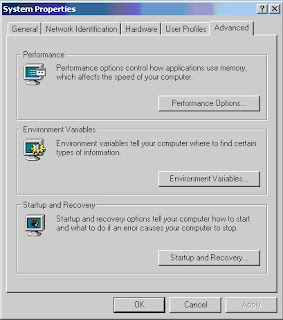
Start > Settings > Control Panel > Add or Remove Program >
Add or Remove Programs > Add/Remove Windows Component >
Management and Monitoring Tools > Simple Network Management Protocol.
• Download Perl (www.activestate.com)

1. Double click to start the installation and Next to proceed.
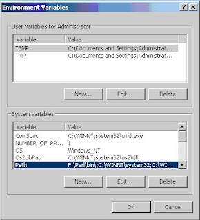
2. To verify the Installation:


(clear view image)

See the path listed under System Variables


(clear view image)

• Download MRTG (www.mrtg.org).
1. WinZip MRTG (preferably in same drive as of Perl)
2. Create another folder “mrtghtml” (can be any sensible name) to hold graph files.
3. Run cfgmake: Run following command on command prompt
c:\mrtg\bin> perl cfgmaker public@ --global "WorkDir: c:\mrtghtml" --output server.cfg.


4. Run Indexmaker: Run following command on command prompt
c:\mrtg\bin> perl indexmaker --output intel510t.htmintel510t.cfg"- -output

intel510t.htm" is the name of the webpage output file. Be sure and use the "htm” extension
"intel510t.cfg" is the name of the configuration file you want to use in making an index of targets

5. Running MRTG: Run following command on command prompt
perl mrtg server.cfg

6. Running MRTG as a Daemon:
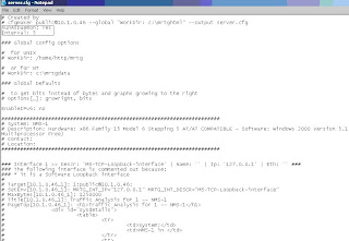
Open server.cfg with notepad (C:\mrtg\bin\server.cfg) and add these lines: RunAsDaemon: Yes
Interval: 5


(clear view image)
7. Return to DOS window and run MRTG again and don’t close the window else MRTG will die!!!